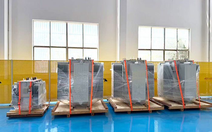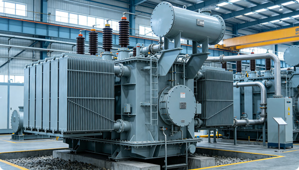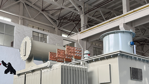


Working principle and introduction of magnetic voltage regulator
Magnetic voltage regulator is a voltage regulating device that combines a saturation reactor with a transformer. Among them, the reactor is mainly responsible for regulating the input voltage of the transformer, while the transformer increases or decreases the adjustable input voltage to any voltage value required by the load. There is both electrical and magnetic connection between the two, similar in structure to a general power transformer, but different from other types of voltage regulators - it does not have a mechanical transmission device or movable contacts. The characteristic of having no contact or mechanical moving parts makes it particularly suitable for high voltage output or low voltage high current output situations. At present, voltage regulators such as salt bath furnaces, electron bombardment furnaces, and high-voltage electrostatic precipitators have been widely used in voltage regulating power supplies.
Basic Structure and Circuit Relationship
A magnetic voltage regulator consists of two parts: a reactor and a transformer. The reactor is equipped with an AC working winding and a DC control winding, while the transformer is equipped with a primary winding B1 and a secondary winding B2. The AC working winding G of the reactor is connected in series with the primary winding B1 of the transformer, forming an electrical connection between the reactor and the transformer.
Working principle
The voltage regulation process of a magnetic regulator is essentially to use DC control current to change the magnetization state of the reactor core, thereby changing its AC effective magnetic permeability and impedance, and ultimately achieving continuous regulation of the load voltage.
When the input terminal of the magnetic voltage regulator is connected to voltage U1 and the output terminal is connected to the rated load resistance R, if the DC control current Ik=0, the reactor core is not magnetized by DC. At this time, the effective magnetic permeability of AC is large, and the impedance reflected on winding G is much larger than the total primary impedance of the transformer. Therefore, the power supply voltage U1 is basically distributed on winding G, while the primary side voltage UB1 of the transformer is very small, and the load voltage is at the lower limit value U2min.
Gradually increasing the DC control current Ik, the reactor core is subjected to varying degrees of DC magnetization, and the effective AC magnetic permeability gradually decreases. As a result, the voltage on winding G and the load voltage U2 gradually increase. When Ik reaches the rated value Ika, the core of the reactor is highly magnetized by DC and saturated, and the effective magnetic permeability of AC becomes the smallest. The impedance of the reactor is also the smallest compared to the total primary impedance of the transformer. At this point, the power supply voltage U1 is basically distributed on winding B1, and the load voltage U2 can reach its maximum value U2max.
It can be seen that by continuously adjusting the magnitude of the DC control current Ik, smooth and stepless adjustment of the load voltage U2 from the lower limit to the maximum value can be achieved. The entire process has no mechanical action, no contact switching, and a smooth response, which is the core advantage that distinguishes magnetic voltage regulators from traditional voltage regulation methods.